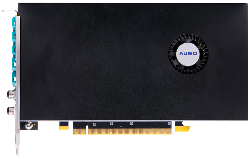
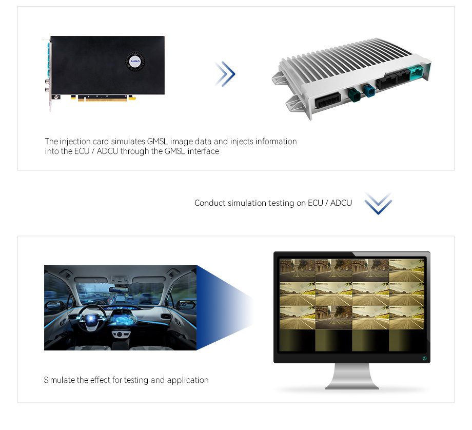
Based on Xilinx ZYNQ Ultrascale+ MPSoC series FPGA chip design, it is applied in the fields of autonomous driving such as injection image simulation, in-vehicle video playback, hardware-in-the-loop HIL simulation, etc.
Solution provided for algorithm validation and optimization in the autonomous driving industry
3840 × 2160@30fps support up to 8-way output
PCI Express Gen 3 x 16
Support gPTP timestamp with time service, with the accuracy of less than 1 ms
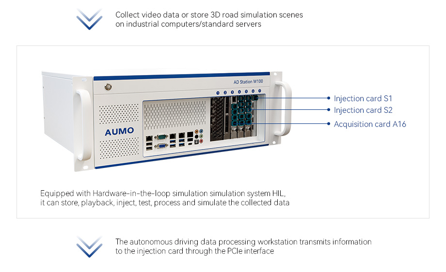
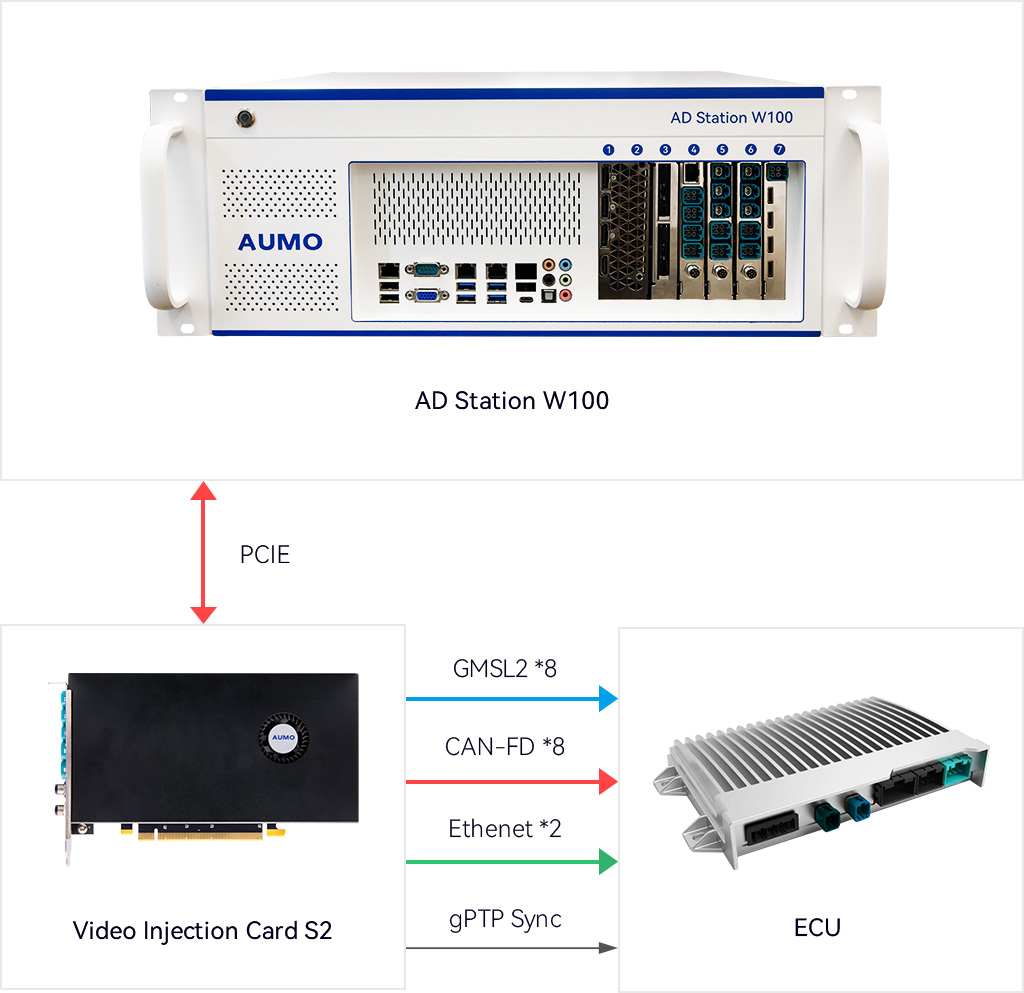
AD Station W100 is a research and development platform for autonomous vehicle acquisition, calculation, and hardware in the loop simulation testing of HIL. It can be paired with 16 channel in car camera GMSL acquisition card A16, 8 channel in car video injection card S2, and 4 channel in car video injection card S1
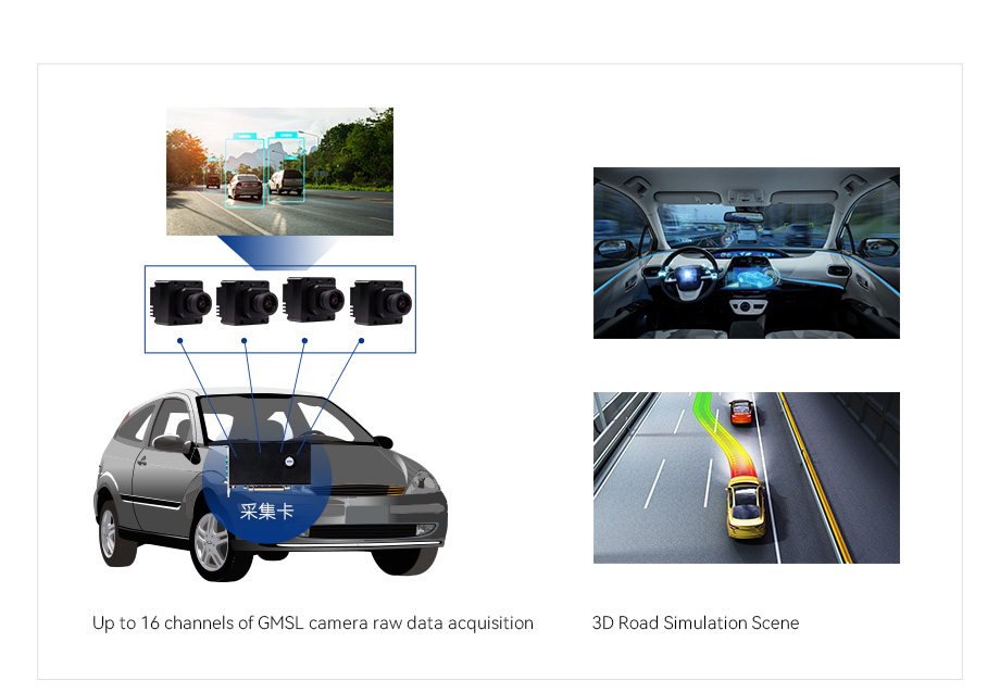
Serializer
Supports MAX96717, MAX96717F, MAX9295A, MAX96715, etc
Correspondin g deserializer
Support MAX96712 / MAX9296A and so on
CAN
8 CAN / CAN-FD interfaces
Number of channels
8-way camera video output
Video format
YUV422、RAW12
PCIE
PCI Express Gen 3 x16
Output Resolution
4096×2160@30fps support up to 8-way output
FAKRA
4-in-1 Amphenal Z code min-Fakra
External trigger
Support the synchronization of the external trigger of cameras
Vehicle Ethernet
3 × 1000M Base-T1 interface Support gPTP timestamp with time service, with the accuracy of less than 1 ms
Cable length
Under GMSL1 mode can reach 40m (3Gbps)
Under GMSL2 mode can reach 20m(6Gbps)
Upgrade
Support the upgrade of PC firmware
operating system
Linux / Windows
Working temperature
-40℃~70℃
Storage temperature
-40℃~85℃
Working Humidity
10%~90%
Storage Humidity
0~90%
Power supply
PCIE Power supply / 12V Power supply
Weight
400g
Size
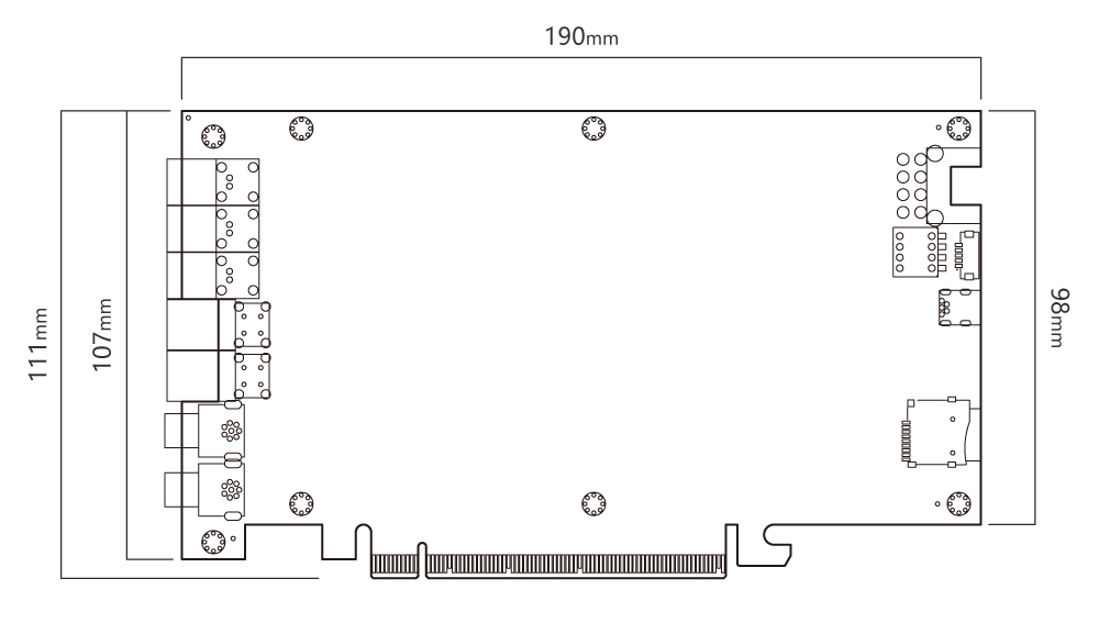
Length* Width:111.15 * 189.99(mm)
MTBF
5 years
3-way 1000BASE-T1 interface, 2-way 4-in-1 Amphenol min-Fakra interfaces (8-way video output), and 2 M8 aviation socket (including 8-way CAN/CAN-FD interfaces) are led out at baffle as the external interfaces

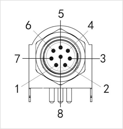
Using M8 8pin aviation socket (male) for CAN/CAN-FD bus communication
PIN
1
CAN1_H
Two-way
CAN_H signal wire
2
CAN1_L
Two-way
CAN_L signal wire
3
CAN2_H
Two-way
CAN_H signal wire
4
CAN2_L
Two-way
CAN_L signal wire
5
CAN3_H
Two-way
CAN_H signal wire
6
CAN3_L
Two-way
CAN_L signal wire
7
CAN4_H
Two-way
CAN_H signal wire
8
CAN4_L
Two-way
CAN_L signal wire
Using M8 8pin aviation socket (male) for CAN/CAN-FD bus communication
PIN
1
CAN5_H
Two-way
CAN_H signal wire
2
CAN5_L
Two-way
CAN_L signal wire
3
CAN6_H
Two-way
CAN_H signal wire
4
CAN6_L
Two-way
CAN_L signal wire
5
CAN7_H
Two-way
CAN_H signal wire
6
CAN7_L
Two-way
CAN_L signal wire
7
CAN8_H
Two-way
CAN_H signal wire
8
CAN8_L
Two-way
CAN_L signal wire
Static power consumption
9.46W
Dynamic power consumption
22.15W
Solution for hardware in the loop testing HIL, which can achieve parallel expansion of multiple boards to increase the number of injection channels.
Used for video simulation of unmanned driving systems
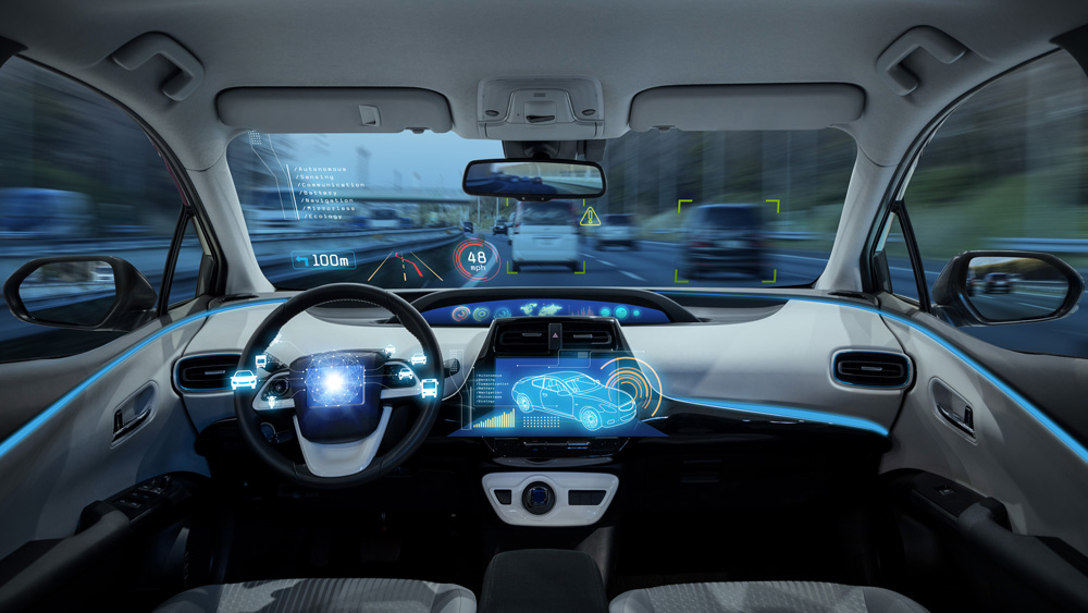
Video playback for data collection vehicles
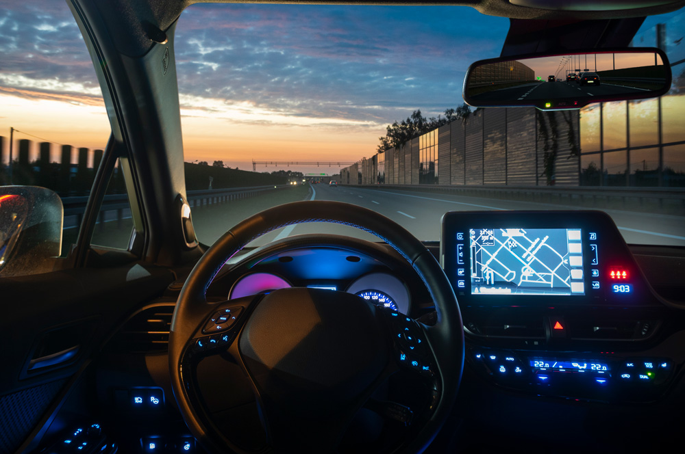
Used for ADAS and autonomous driving test system in loop HIL simulation
